Sunday, October 3, 2010

Design, Even in a Toothpaste Tube

This is one of my sillier endeavors but I think it will make sense to those other like-minded engineers/designers out there.

So, I have a pet peeve: wasting toothpaste at the end of the life of the tube. It bugs me when there's something leftover in any type of container for that matter. But I deal with toothpaste on a daily basis so it is a perpetual nuisance. The solid exoskeleton toothpaste containers seem like they're even worse than the soft tubes that you could squeeze or roll until you're blue in the face.


A couple of days ago I was getting to the end of another solid tube and the frustration got to the point that I had to take it apart just to see how much I was wasting. So I got my exacto and tore into it. To my surprise there was only a small glob of toothpaste at the very tip, only a single toothbrushing-worth.


It had felt like much more than that, not to mention I didn't know how it was possible to have that little in the rest of the foil-like sack. I was about to chock it up to "who knows" when I noticed something on the base.


That's right, whoever designed this achieved a one-way valve with a tiny piece of plastic and a heat-weld with a couple small interruptions for air to pass in only one direction. That allowed it to squeeze as much as possible out of the toothpaste sack. Something so cheap and simple yet innovative to solve man's toothpaste dispensing needs. It's the small things in life :).

Refrigerator Compressor Repair

This Alabamian gave me a non-working wine cooler mini-fridge, half out of generosity because I might be able to fix and use it, half out of wanting to get rid of it :-).

Regardless, I've had this fridge sitting in the middle of my apartment now for the better part of a month. It haunts me every time I walk by it. Sitting there... not working... taking up space. I finally had time this weekend to troubleshoot it.

Symptoms:
After plugging it in,the compressor would hum for 15-20 seconds and then there would be a click and it would be silent for about two and half minutes. Then it would click and the cycle would repeat itself. I let this go on for about 15 minutes while I monitored the temperature inside the fridge. There was no change inside but the compressor was almost too hot to touch. So began the troubleshooting.

Teardown:
I took off the condenser (panel of tubes on the back), removed the thermostat housing and finally pulled out the compressor.


I had to bend some of the brass tubes in the process, being careful not to kink them. All that was let was to pull off a cover exposing the relay and circuitry for the compressor.


Troubleshoot:
The first step was to bypass the thermostat, sending an "always on" to the compressor to eliminate that as a potential problem. Here is the thermostat with the dial and cover removed.


Bypassed


Making sure to not touch any of the exposed contacts I plugged it in again. Same result, so I did a little Google searching and found a convenient How to Test a Refrigerator Compressor article. The takaway from that and a few other forums with posters with similar symptoms was that its either a bad relay, overload protector or compressor. If the compressor is gone then I'm hosed so I decided to check the relay and overload protector.


The overload protector is the small black plastic housing attached to two terminals protruding from the compressor housing. (P6R8MC OR0510, just in case someone searches) The common wire attaches to the overload protector. After taking it off this is that it looks like.


Now after removing the metal securing strip and the cover.


You can see a strange white disc shape that separates the two sides.


As you can see, the two sides of the disc are in different condition. One looks like it has been shocked/burnt and the other is only slightly scratched. I think this disc acts as either a sort of discharge capacitor or a large overload resistor.


Either way, I decided to flip it and put it back in the overload protector. Voila! Whatever contact or circuit that is supposed to make wasn't being made on the destroyed side. Within 20 minutes the fridge was down to 40 degrees! Hopefully this will provide others with some DIY troubleshooting inspiration. And thanks to the Alabamian for the (now working) fridge!

Thursday, July 29, 2010

1992 Nissan Quest Alternator Rebuild

Background:
According to the fellow members of clubxterra.org you can upgrade the Nissan Xterra alternator, which is a measly 85 amps to the 115 amp alternator from the Nissan Quest. (that's a 35% increase for your fellow stat lovers) Depending on which year in the 1989 to 1992 compatible date range, it can be a direct swap or require a minor amount of grinding to get it to fit.

The motivation behind this upgrade stems from the fact that I added a total of six (6) 55 watt Hella 500FF lights, four drivers for the roof rack, and two fogs for the bumper. When I turn on the roof rack lights the engine groans and changes pitch like it has to work twice as hard. When I eventually get some surround lighting or rock crawl lighting or a PA system I’ll tax the alternator even more. So I figure I might as well do this cheap upgrade.

My friends and I took an alternator-hunting trip to Harry’s U-Pull It yard in PA. Out of the thousand or so cars that we canvassed there were only two matches and one of those looked half descent. It ended up costing around $16 plus a $3 core and we scored a bunch of other random bits and pieces of trim that I needed from a 2002 Xterra so the trip was well worth it.

The first step after acquiring my new project alternator was to get it tested at my local auto store. They have a dedicated alternator test cart where they put the alternator in a vise-like apparatus, connect some electrical leads and then attach a drive belt. They run it for a minute or so and determine the average voltage output. Your average alternator should be putting out around 14V (yes cars have 12V electrical systems, but this is directly out of the alternator before it’s reduced/capped) but mine was putting out a whopping 10V. Of course it couldn’t be that easy.

So the next step was to take it apart and see if I, having no experience with alternators, could see an indication of why it wasn’t producing full volts.

Teardown:
1. Remove the bolts holding the two halves of the alternator together. One half includes the coil and is the stator. The other half includes the bearing support for the rotor.

2. Pry the two halves apart. This is much easier said then done. I ended up standing with the stator half down and pulling on the rotor pulley. Needless to say when it came apart I nearly fell over.

3. Remove the two bolts located at 5 and 7 o'clock positions that retain the brush housing.


4. Using a soldering iron melt the solder connecting the two tabs to the rest of the alternator. This was by far the trickiest part. It was a very high temperature solder and I had to hold the soldering iron on for a good 30-60 seconds before there was enough residual heat in the part for the solder to turn liquid. I then had to scrape enough of it away from the tab connection and use a pair of plyers to make sure it remained disconnected as the solder solidified.


5. Remove the brush housing. You can clearly see the broken portion of the brush in this picture.


6. After removing a rubber endcap it exposes the two terminals which the correspond to each of the two brushes.


7. Once again I had to use the soldering iron to melt the solder in order to remove the brush-spring-contact assembly. Interestingly, the brush is formed with a copper wire coming out of it which travels in the center of the spring and connects to the metal tab at the bottom. I guess the spring connection wasn't sufficient (or efficient) enough to conduct the power.


8. Originally my buddy Alex had suggested that I get some graphite (the material the brushes are made out of) stock and cut/shave it down to size to replace the broken brush. But seeing as they have integral wires I don't think that's an option any more. Now I need to figure out where I can get a rebuilt kit or parts for the Quest Alternator... ideas?

Friday, July 16, 2010

1967 Wheel Horse Tractor Gearbox Teardown


Background:
So, my Dad and I have always been proud that we have a working tractor from 1967. For me personally it brings back some fond memories. I can remember my Dad pulling us behind it on sleds when it sleeted for the first time in Houston, TX. We hauled it from there to Michigan about a decade ago and it's been used for odd jobs and the occasional mowing of the lawn. It wasn't until my buddy convinced me a couple summers ago to attend a tractor fair somewhere in CT that I realized just how many other antique tractor enthusiasts there are... so much so that it's more of a cult following, especially Wheel Horses.

One of these odd jobs took its toll on the ol' girl last summer (2009). My Dad and I decided that there were some limbs that were too close for comfort to the new garage that we built. In some cases they were lightly touching and in others they were simply overhaning with the potential to get weighted down with snow and hit the building. In any case, we decided to take it upon ourselves to cut down some decent sized trees/limbs. They ranged from a few inches in diameter to one that was a good 8". Being the lazy efficient people we are, we decided to use the wheel horse to tow the trees over to the burn pile after they were cut down. The last tree, the straw that broke the wheel horse's back *cough* Dad *cough* was driving the wheel horse and had to get a rolling start combined with a pop-a-wheelie to get the tree moving. Naturally something broke and the wheel horse wouldn't go into neutral and after messing with it for a few minutes with the brake applied to remain stationary it started smoking - either from the belt or the brake... or both.

Long story short, we broke something and this summer we tasked ourselves with finding out what. After a short troubleshooting session which resulted in the tractor tearing out of the garage unmanned we decided to take it apart and I volunteered to take the gearbox home and dissassemble it.

Teardown:
Cut back to my one bedroom apartment in Schenectady. I may have took on a project that I didn't exactly have room for. Decide for yourself: (yes that's a spatula)


My kitchen is officially a chop shop now. Here's the steps that I took dissassembly the gearbox, more for my benefit than anything else.

1. Drain the gearbox oil
2. Remove set screws for wheel hubs
3. Remove wheel hubs and half-moon key


4. Unbolt and remove brake shoe
5. Remove snap ring retaining brake wheel and remove brake wheel


6. Remove set screw on drive pulley
7. Remove drive pulley
8. Remove snap rings on either side of the hitch
9. Remove the hitch pin and hitch. A punch was required to remove the pin.
10. Unbolt the six (6) casing bolts around the exterior that hold the two halves of the gearbox together.
11. Pry the two halves apart using a screwdriver or thin prybar. Make sure to have
something to catch the remaining oil.


12. Lay the gearbox on its left side using supports to make it level and remove the right side of the casing.


The above and below picture show the gearbox in the configuration immediately after removal. Note the position of the two sliding rails that the end of the gear lever sets in.


For this picture I simply put the gearbox into gear and in doing so moved the left shifting rail. This would typically take the second shifting rail along for a ride but as you can see the rail is sheared at the semicircular collar so it stayed in position.


Here are the rails after I removed them. One thing that I found interesting, in order to achieve the feel and function of engagement positions (other than the gear meshes) there were grooves in the rail shafts which mated with a spring and ball bearing in the casing hole which the rails slide in. Such a simple solution yet very robust.


Here's my makeshift workbench/garage. The cleanup was not fun and my place still smells like gearbox oil.


Now begins the hard part. I need to find a replacement rail and potentially a gasket/seal for reassembly. Worst case I can just use a gasket maker and reuse the seal. I can either go the online route (forums or ebay) or try and find a tractor event within a couple hours that has a parts section.

Wheel Horse Links:
http://www.mywheelhorse.com/
http://www.bellshome.com/shows.htm
http://www.neatta.org/
http://whtractor.15.forumer.com/

Wednesday, June 16, 2010

Life Suggestions

How many times have you gone to Google.com and entered in a random question. Often we treat the Google search engine as if it were the Deep Thought from Hitchhiker's Guide to the Galaxy. Deep Thought was commissioned to answer the question, "what is the meaning of life." The numerical result was of course, 42. Before we even get to the answer that we seek our Google search query, we are given the answer to a different question in the form of search suggestions. Before typing your question, as if being interrupted by a crowd of midgets on sugar highs, suggestions for the top 10 popular (but filtered I'm sure) searches appear.


These search suggestions are a mirror into our species. A compiled and condensed list of the most common burning questions on our collective minds. We may not like or even agree with what's there but there's no denying it. Especially when scanning the suggestions you find yourself wondering what the answers to some of them are and you're fighting the urge to search.

So here's my challenge, can you complete (and thus answer) all of the top 10 how-to questions of the human race at the same time? Now where's my rubix cube and my dragon.

Friday, April 30, 2010

TI-89 Calculator and 40D - Time-Lapse Magic

I was first inspired by this project by an instructable sent to me by a friend that shows you how to turn your TI calculator into an intervalometer which can then be used for time-lapse photography/videography.

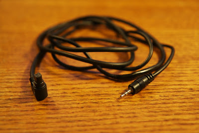
However, the camera used as an example in the instructable has a standard 2.5mm mini-plug instead of the N3 plug that my 40D has. So I needed to figure out how to get from the 2.5mm jack on the TI-89 to the N3 plug on my camera. It turned out to be pretty simple, order a remote shutter release cord and a 2.5mm cord and splice them. Here's the step-by-step:

1. Supplies
2.5mm cord
N3 shutter release
Wire cutter/striper
Electrical tape
Solder and soldering iron (optional)


2. Cut the wires


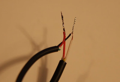
3. Cut back about an inch of the outer sheath exposing the individual wires and strip the about a half an inch. Remember these wires only have half a dozen strands so they're very delicate.


4. You should have 3 from the N3 cable (Red - Shutter, Yellow - Focus, White - Common) and 4 from the 2.5mm cable (Black - Common, Red - supply, Green, White). If your colors are different you're going to need to use a bit of trial and error. I found it useful to open up the shutter release button, or take a look at this helpful diagram.


5. First try connecting the N3-white to the 2.5-black and the N3-red to the 2.5-red. Run the program on your TI. Make sure your camera is turned on and focused properly or in manual focus mode. If your camera snapped some pictures then great, your almost done! If not, then my suggestion is to use a multimeter to find the common on the 2.5mm side, connect it to the common on the N3 and then just through trial and error (twist the N3-red with each one of the other colors and run the program) determine which wire activates the shutter.


6. Once you have the correct wires you can solder them together for a more durable connection (optional)


7. Tape the connection up and you're done! Hope this helps, please post comments with questions or successful videos!